
Aug 26, 2026Technical Articles
Narrow-Channel Impeller 3D Printed Sand Casting | Sintered Ceramic Sand
Binder jetting 3D printed sand molds for narrow-channel impellers: process, sintered ceramic foundry sand selection, defect control and production guidance.
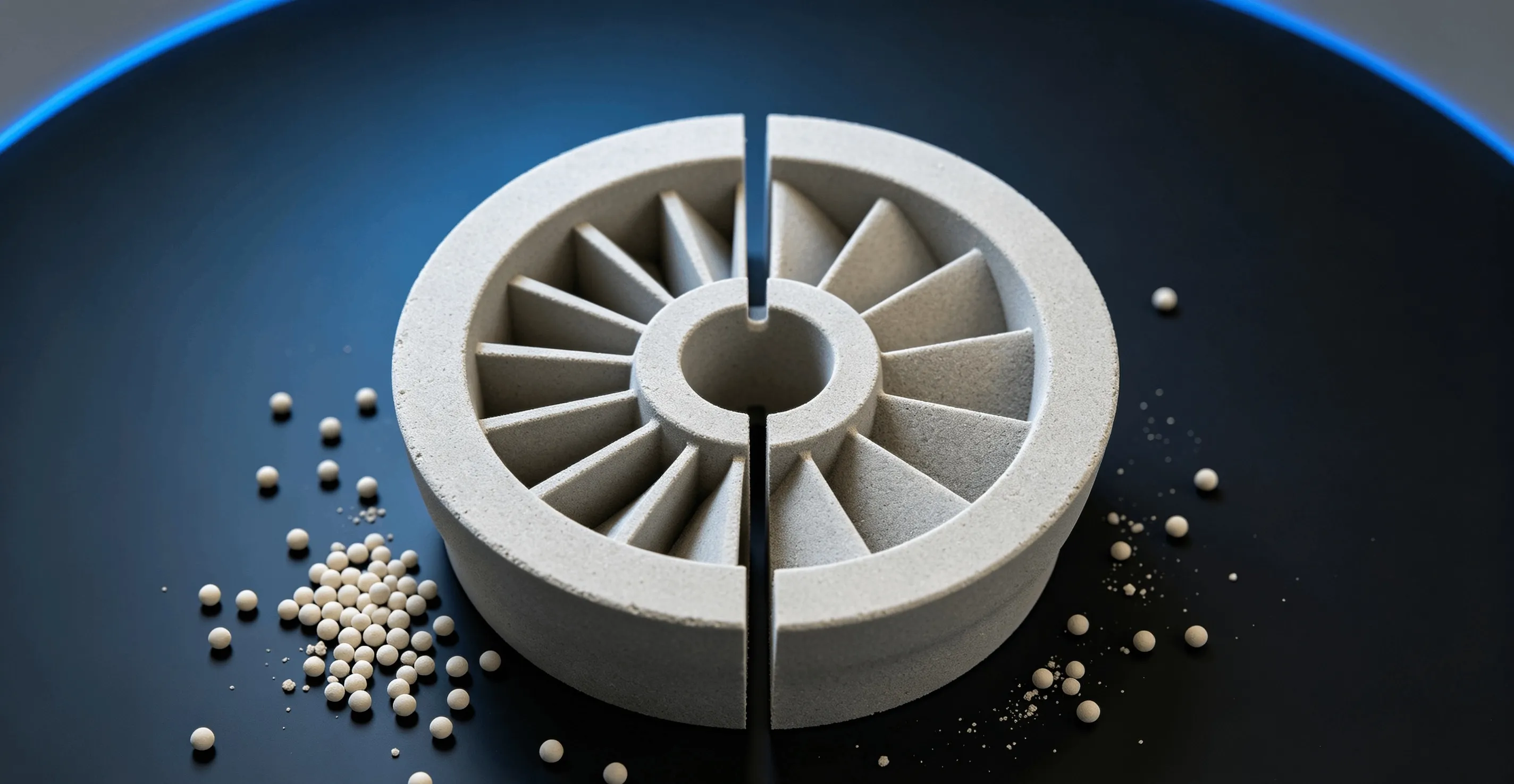
Pump impellers — especially narrow-channel designs with outlet widths ≤6 mm, double-suction impellers with dual-layer blades, and highly twisted profile blades — have long been constrained by the assembly accuracy and surface quality limitations of conventional core-making. Binder Jetting 3D sand printing enables complex internal cores to be fabricated in a single piece via digital layer-by-layer forming, eliminating assembly gaps and opening a new manufacturing path for narrow-channel impeller castings.
1. Process Principle
The core workflow of binder jetting 3D sand printing:
- Sand spreading: A recoater deposits a uniform layer (0.2–0.5 mm) of foundry sand (70–140 mesh) pre-mixed with a hardener onto the build platform.
- Binder deposition: An inkjet print head selectively deposits furan resin binder onto the sand layer according to the CAD cross-section; the binder reacts with the hardener to locally cure the sand particles.
- Layer-by-layer build: The platform descends by one layer thickness; spreading and deposition repeat until the complete mold/core is printed.
- De-powdering and post-processing: Unbound sand is removed; optional thermal curing produces a mold ready for pouring.
Unlike the point-wise scanning of Selective Laser Sintering (SLS), binder jetting is a line-/area-wise process, delivering higher throughput without laser hardware — making it better suited for volume sand mold production.
2. Advantages for Narrow-Channel Impellers
Dimension | Conventional Core Assembly | 3D Printed Monolithic Core |
|---|---|---|
Channel forming | Multi-core assembly with joints and misalignment | Monolithic forming, zero assembly gap |
Dimensional accuracy | Affected by tool wear and cumulative assembly error | ±0.3 mm, digitally controlled |
Surface quality | Flash and mismatch at joints | Continuous internal surface, significantly improved Ra |
Lead time | 4–8 weeks for tooling | 3–5 days from CAD to mold |
Low-volume economics | High tooling amortization | No tooling cost, controllable unit price |
3. Material Selection: Why Sintered Ceramic Foundry Sand
3D printed sand molds impose different demands on foundry sand compared with conventional processes: excellent flowability (for uniform spreading), appropriate grain size distribution (balancing surface finish and permeability), low thermal expansion (to suppress veining), and low gas evolution (to reduce porosity risk).Sintered Ceramic Foundry Sand is a spherical artificial sand produced from bauxite via high-temperature sintering. Key properties:
- Grain shape: Spherical, angularity factor ≤1.1 — excellent flowability and uniform spreading.
- Refractoriness: ≥1800 °C — suitable for steel, iron and high-temperature alloy casting.
- Thermal expansion: 4.0–6.0 × 10⁻⁶/K (20–1000 °C), far below silica sand (~12 × 10⁻⁶/K) — effectively suppresses veining.
- Gas evolution: Low gas emission — mitigates porosity risk from the relatively high binder content in 3D printed molds.
- Grain size: AFS 40–70 available; AFS 50–55 is the common 3D printing grade, balancing surface finish and permeability.
- Chemical inertness: Al₂O₃-based, chemically neutral — no mold–metal interface reaction.
For narrow-channel impellers with restricted internal cavities and poor heat dissipation, silica sand's phase-change expansion at high temperature readily causes veining on channel surfaces. The low thermal expansion of sintered ceramic sand reduces veining at the material source, cutting downstream grinding workload.
4. Common Defects and Control Measures
Defect | Cause | Control Measure |
|---|---|---|
Veining | Mold thermal expansion cracking; metal penetrates cracks | Use sintered ceramic sand to reduce expansion; optimize mold wall thickness; apply anti-veining coating |
Gas porosity | Binder pyrolysis generates gas | Control binder saturation; fully cure molds; improve permeability; use low-gas ceramic sand |
Sand inclusions | Insufficient mold strength or incomplete de-powdering | Optimize binder saturation; post-cure to strengthen; thorough de-powdering |
Dimensional deviation | Improper layer thickness or mold deformation | Use 0.3 mm layer thickness; control ambient T/RH; avoid prolonged mold storage |
5. Production Recommendations
For volume production of narrow-channel impellers via 3D printed sand molds, we recommend:
- Validate with prototypes first: Pour initial impellers using 3D printed molds to confirm dimensional accuracy and surface quality.
- Standardize materials: Lock the AFS grade (recommended AFS 50–55) and binder system; establish batch inspection criteria.
- Freeze print parameters: Define layer thickness (0.3 mm), binder saturation, curing temperature and time — formalize as SOP.
- Cost analysis: 3D printing is typically cost-competitive at volumes ≤50 units/year vs. conventional tooling.
Learn more about sintered ceramic foundry sand for 3D printed sand molds: View Sintered Ceramic Foundry Sand.